Baru-baru ini Microsoft meluncurkan windows terbarunya " Windows 8". Kita tidak membahas kelebihan atau kekurangan cuman Soundthemes nya enak didengar. tanya om google nah ketahuan siapa penyanyinya.
Lenka - Everythink at once album Two.
Tuesday, October 30, 2012
Best List of Freeware and Open Source Programs
3D Graphics
3Delight Free - http://www.3delight.com/index.htm
Anim8or - http://www.anim8or.com/
Aqsis - http://www.aqsis.com/
Blender - http://www.blender3d.org/
gmax - http://www.discreet.com/products/gmax/
Houdini (Free Edition) - http://www.sidefx.com/apprentice/index.html
Maya Personal Learning Ed. - http://www.alias.com/eng/products-services..._maya_ple.shtml
Now3D - http://digilander.libero.it/giulios/Eng/homepage.htm
OpenFX - http://www.openfx.org
POV-Ray - http://www.povray.org/
SOFTIMAGE|XSI EXP - http://www.softimage.com/products/exp/v3/
Terragen - http://www.planetside.co.uk/terragen/
Toxic - http://www.toxicengine.org/
Wings 3D - http://www.wings3d.com/
Soundthemes Iklan Chevrolet Aveo
Sudah sering saya lihat iklan Chevrolet Aveo, ada yang menggelitik hati, soundthemes nya enak didengar. Coba-coba search di google akhirnya ketemu. Sound themes ini dinyanyikan oleh Fun "We Are Young"
Friday, October 19, 2012
Best List of Freeware and Open Source Programs 3D Graphics
Best List of Freeware and Open Source Programs
3D Graphics
3Delight Free - http://www.3delight.com/index.htm
Anim8or - http://www.anim8or.com/
Aqsis - http://www.aqsis.com/
Blender - http://www.blender3d.org/
gmax - http://www.discreet.com/products/gmax/
Houdini (Free Edition) - http://www.sidefx.com/apprentice/index.html
Maya Personal Learning Ed. - http://www.alias.com/eng/products-services..._maya_ple.shtml
Now3D - http://digilander.libero.it/giulios/Eng/homepage.htm
OpenFX - http://www.openfx.org
POV-Ray - http://www.povray.org/
SOFTIMAGE|XSI EXP - http://www.softimage.com/products/exp/v3/
Terragen - http://www.planetside.co.uk/terragen/
Toxic - http://www.toxicengine.org/
Wings 3D - http://www.wings3d.com/
Anti-Virus
AntiVir - http://www.free-av.com/
Avast - http://www.avast.com/i_idt_1018.html
AVG - http://free.grisoft.com/
BitDefender - http://www.bitdefender.com
ClamWin - http://www.clamwin.com/
Avast - http://www.avast.com/i_idt_1018.html
AVG - http://free.grisoft.com/
BitDefender - http://www.bitdefender.com
ClamWin - http://www.clamwin.com/
Penyebar Foto Tidak Senonoh Novi Amilia Dicari Polisi
Jakarta Polisi tidak tinggal diam melihat foto tidak senonoh Novi Amilia yang tersebar. Dalam foto yang diambil di markas polisi sesaat setelah kejadian itu, Novi berpose tak pantas. Bagian pribadi Novi terlihat dalam foto itu.
"Sekarang pada saat kejadian, semua bercampur baur. Ada masyarakat, ada polisi, ada media, berada dalam posisi yang sama ingin melihat pelakunya. Polda Metro sedang mencari pelakunya, siapa yang memfoto dan menyebarkannya. Kita lagi cari dulu," jelas Kabag Penum Mabes Polri Kombes Pol Agus Rianto di Mabes Polri, Jl Trunojoyo, Jakarta, Rabu (17/10/2012).
"Sekarang pada saat kejadian, semua bercampur baur. Ada masyarakat, ada polisi, ada media, berada dalam posisi yang sama ingin melihat pelakunya. Polda Metro sedang mencari pelakunya, siapa yang memfoto dan menyebarkannya. Kita lagi cari dulu," jelas Kabag Penum Mabes Polri Kombes Pol Agus Rianto di Mabes Polri, Jl Trunojoyo, Jakarta, Rabu (17/10/2012).
Free Download Antivirus
| |||||||||||||||||||||||||||||||


office freeware
Office
OpenOffice - office suite
PC Suite 602 - office suite
AbiWord - text editor
Atlantis Nova - text editor
Microsoft PowerPoint Viewer - power point files viewer
Adobe Reader - pdf reader
Foxit PDF Reader - pdf reader
PDFCreator - create pdf documents
PC Suite 602 - office suite
AbiWord - text editor
Atlantis Nova - text editor
Microsoft PowerPoint Viewer - power point files viewer
Adobe Reader - pdf reader
Foxit PDF Reader - pdf reader
PDFCreator - create pdf documents
Monday, August 27, 2012
Arti Kode pada Ban
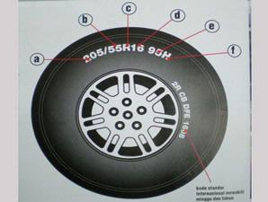
"Pakai ban ukuran berapa?," tanya penjaga toko ban. "15 dan lebar 195," jawab pemilik kendaraan. Hanya dua kode itu, barangkali yang dipahami atau diketahui umumnya pemilik kendaraan. Bahkan, jangan-jangan, angka 195 yang disebut tadi, meski tahu kalau yang dimaksud lebar, tapi tidak tahu yang sisi mananya.
Monday, May 28, 2012
Forex Thrading
Marketiva ( AGEA )Adalah Broker Paling " Recomended " di anjurkan bagi para pemula yang ingin terjun di bidang Forex online trading.
Selain aman juga mudah untuk melakukan deposit maupun withdraw ( penarikan dana ) , anda juga akan mendapatkan Bonus 5 $ untuk pertama kali daftar .
jika Anda Belum terdaftar silahkan Klik Disini Untuk daftar
Cara Trading di Marketiva sangatlah mudah, setelah anda membuka account serta download dan install streamster, lalu login ke Streamster dengan account Marketiva anda.

Cara termudah untuk memulai trading adalah dengan mengklik pada instrumen pasar di window harga. Ketika dialog [Send Order] muncul, anda bisa set kolom [Quantity] menjadi 100 atau lebih (tergantung pada jumlah yang anda miliki pada trading desk tersebut). Ketika anda mengklik tombol OK, order tersebut akan masuk ke market.
 penjelasan :
instrument : adalah mata uang yg ingin anda perdagangkan
Selain aman juga mudah untuk melakukan deposit maupun withdraw ( penarikan dana ) , anda juga akan mendapatkan Bonus 5 $ untuk pertama kali daftar .
jika Anda Belum terdaftar silahkan Klik Disini Untuk daftar
Cara Trading di Marketiva sangatlah mudah, setelah anda membuka account serta download dan install streamster, lalu login ke Streamster dengan account Marketiva anda.

Cara termudah untuk memulai trading adalah dengan mengklik pada instrumen pasar di window harga. Ketika dialog [Send Order] muncul, anda bisa set kolom [Quantity] menjadi 100 atau lebih (tergantung pada jumlah yang anda miliki pada trading desk tersebut). Ketika anda mengklik tombol OK, order tersebut akan masuk ke market.
instrument : adalah mata uang yg ingin anda perdagangkan
Quantity ; adalah jumlah
yang akan anda perdagangkan jika anda isi 100 maka 100 point = 1 $
artinya jika posisi anda profit ( Hijau ) 100 point
berarti anda untung 1$ . begitu juga sebaliknya jika posisi anda Loss (
Merah ) 100 point berarti andaRugi 1 $.
Monday, April 16, 2012
3D Coordinate system | Rotation in 3D
THE 3-D CO-ORDINATE SYSTEM
By now you should be very comfortable working your way around the X-Y coordinate system. Anyway, here is a quick review. Looking from the plan (top) view, this is what you see to figure out where is positive X and positive Y.
If you were to look at the same picture, but at a slight angle, you would see the third axis. This new axis is called the Z-axis. Imagine that the positive Z-axis is coming towards you out of the monitor.

The Z-axis has always been there, lurking in the background, waiting for you.
When you entered points previously, you would enter them in the format: X,Y. By doing this, you let AutoCAD know that in these cases, Z was equal to zero. Entering 4,3 would be the same as entering 4,3,0. Now if you drew a line from the origin (0,0,0) to a point at 4,3,2, you would get a line that goes 4 inches to the right, 3 inches up and 2 inches towards you. The properties of this line would be this:
 Dialog Box")
Notice that the line is actually 5.3852" long. If you were to look at it from the plan view, it would look exactly like a line drawn from 0,0 to 4,3 Draw a line from 0,0 to 4,3 and then compare the properties.
The diagrams below, show this line from 4 different views to illustrate how things can look different in 3D. Look at each one carefully, and see if it makes sense to you.
 |
This is the usual view you have seen when using AutoCAD in 2D. You are looking straight down the Z axis (positive Z is pointing at your). It looks like any other line you have drawn, going from 0,0 to 4,3 - but there is a difference...
|
 |
If you were to look at the line from the front, instead of the top (as shown above) you would be able to notice the elevation of 2 units in the Z axis. This is the same line as above, only viewed from a different angle. In this view, you are looking straight down the -Y axis.
|
 |
Just for fun, here is the same line but viewed from the left. This would be looking down the -X axis.
|
 |
Finally, here is the line as viewed in 3D space from the Southeast view. This is where viewing 3D objects on a 2D monitor gets tricky. You need to visualize the Z Axis.
|
What the above images show you is that you will have to get used to looking at a 3D world on a 2D monitor. In each image, the black line looks flat, but you have to use your reference points to determine where it truly is. If you don't understand this perfectly right now, don't worry. It's just an exercise to expose you to 3D viewing. As the lessons progress, you will get much more familiar to this.
Why is this important to look at before entering the world of 3-D? If you were to only look at a 3-D model from the plan (top) view, you would not be able to see any difference between the two lines. (Draw them and see for yourself) On a 3-D model, you can easily have many points over top of each other. This would be very difficult to work with. You may think you're snapping to a particular endpoint, but the reality of it could be very different (think of how the top of the wall looks the same as the bottom of the wall if you're looking straight down it). Fortunately, AutoCAD provides different viewing options for 3-D drafting. This will be discussed in a later lesson, but for now, if you want to see your 2 lines in a view similar the Z-Axis image above, go to your menu called View > 3D Views > SW Isometric. You'll see the lines that look identical in the top view, look very different when viewed from an angle.
Now for the confusing part. You already know how to rotate 2D objects, but you also have to know how AutoCAD measures angles of rotation in 3-D. There is a somewhat simple rule for this called "The Right Hand Rule". To figure out which is the positive rotation angle, imagine that you are wrapping your right hand around the axis with your thumb pointing towards the positive end. The direction that your fingers are wrapped is the positive direction. This applies to all three axes.

DIRECTION OF POSITIVE ROTATION
The main point of this lesson is to tell you that objects can trick you in 3D space. Shortcuts don't always work, you have to be careful with Osnaps and your drawing can turn into a mess very quickly if you're not paying attention. Trust me, I've seen enough students take the easy route and have to start over. If you want to learn 3D, review each lesson before progressing. Make sure you know the concepts inside and out. This is just an introduction to the concepts, you will learn more in the following lessons. You may still want to refer back to this tutorial, though.
AutoCad - Isometric Drawing
Using Isometric commands is one of the simplest ways to give a 3-D representation while using only 2-D commands. This has been the usual way of doing things before CAD allowed true 3-D work to be done. Many times an isometric drawing is used to compliment or give more information to a 3 view orthographic drawing. See the sample below.
You can see that it is a very simple drawing. This basic isometric drawing of the object gives a very good idea of what it looks like. If this is all that is needed then isometric works well. Unfortunately, as soon as you change anything, like the block's height, you'll need to redraw all four views.
AutoCAD has a command called ISOPLANE which allows you to easily draw at a 30 degree angle as needed for an isometric drawing. You can switch between the three 'isoplanes' (top, right, left) by using this command or by pressing the F5 key.
Command: ISOPLANE
Current isoplane: Right
Enter isometric plane setting [Left/Top/Right]: T
Current isoplane: Top
Current isoplane: Right
Enter isometric plane setting [Left/Top/Right]
Current isoplane: Top
By invoking this command, AutoCAD is now set to draw on the top isoplane. Your other choices would be Left or Right. Your first exercise will be to draw the object shown above using isometric methods.
Exercise 1 - ISOMETRIC DRAWING
Begin a new drawing using the acad.dwt template
Create a layer called OBJECT and give it a green color. Make this your current layer.
Type in DDRMODES to bring up the Drawing Aids dialog box. Make your settings the same as what you see below (just turn on Isometric Snap).
Press OK and you'll see that the grid is set up for isometric drawing for the left isoplane in 1/2" increments. Your crosshairs are now angled to show you which isoplane you are currently on and the Grid is laid out differently from what you may be used to..
Begin by drawing the left side of the box (shown at the top of the lesson) using the line command. Ignore the hole at this point. You will want to use the Direct Distance Entry System for this exercise and make sure that you have Ortho (F8) and Osnaps (F3) turned on.Switch to your right isoplane (F5) and draw the right side.
Switch to your top isoplane (F5) and draw the top view.
Create the angle lines to add the angled surface.
Switch back to the left isoplane and start the ELLISPE command. At the command prompt, press I for isocircle. This will allow you to create an ellipse at the correct angle based on the radius of the circle in the orthographic drawing. Use the Osnap to pick the correct center point.
Save your drawing in your CAD folder.To dimension an isometric drawing, you have to do a few things first. Create a text style called Left, and give it a 30o obliquing angle, then create another called right with a -30o obliquing angle. Then create a new dimension style that has the text aligned with the dimension line. After you have placed a dimension, use the DIMEDIT command to change the obliquing angle of the dimension + or - 30 degrees. You may also need to use the properties to change the text in the dimension to left or right depending upon the orientation of the dimension.
Keep in mind that this is still only 2D. Remember that in some instances, it may be quicker and easier to use this method rather than the more complex 3-D methods you'll be learning in the following lessons.
Dimension Styles
Concept: A drawing needs to contain certain information. Most drawings will show you what the object is (as clearly as possible) but won't tell you everything unless you dimension it. Would you agree to buy a house just by looking at the floor plan if it wasn't dimensioned? Would manufacturers know how to build your product if you didn't dimension it? You can see how important it is that a drawing used to convey information must have clear, accurate dimensions. In previous lessons, you have done some dimensioning (first was Lesson 1-8). To continue with this lesson, you should at least have a good concept of basic dimensioning. There are many ways to dimension a drawing, each drafting discipline has it own set of "rules". For example, a drawing of a gear would use a different style of dimensioning than that of a subdivision. My background is in mechanical drafting, so I use that discipline as an example of how to work with setting your dimensions to work with your drawing. Below is an example of how a drawing can be dimensioned:  As you can see, on a simple drawing like this one, only 8 dimensions are needed to convey all the information about the size and shape of the object. With a little more information you can have everything you need to build it. This is the default style you get with the AutoCAD template. Below shows the same drawing, but with added tolerances and note about what the object is made out of.  The changes in the dimensions above were done easily using the DDIM command. This command opens a dialog box for changing the parameters of your dimensions. In this example, the text style was also changed. The great thing about AutoCAD is that it is very versatile. In the case of dimensions, you can modify any component that is part of it. Below are the names of various parts of a dimension:  Also, you can modify the dimension text dramatically, here are some examples:  : :The Dimension Style Manager So now that you have seen what can do - how do you do it? All options are available in the DDIM (Dimension Style Manager) dialog box.  On the left is current style for working with (highlighted in blue). In this lesson, you will create a new Dimension Style and use it in a drawing. From there, you should try different styles and get familiar with the options. Most companies these days will have a standard style (or set of styles) to use on drawings, but this is a very important tool to know if you want to turn out professional looking drawings. Start but invoking the DDIM command and press the NEW button to open the small dialog for entering the name of the style you are creating. In this example I used the name "DIMSTYLE 1".  Make sure that "Start with" has "Standard" as its setting. Press the Continue Button when everything is set. This will open the dialog box for settings, so just press OK to close it for now. Back at the "Dimension Style Manager" dialog box, you will see that the new style you created is listed at the top (left side). To modify it, select the name, then press the modify button. The dialog box opens and click on the second tab (Symbols and Arrows).  As a general rule, I recommend not change much on this tab - especially when you're learning. Set as defaults, the dimensions are sized proportionately, if you change the setting on one parameter, your dimension can look 'off-balance'. For example, you could end up with huge arrows and small text. For the purposes of this lesson, the only thing that will change on this tab is the arrowheads. Select something other than the standard. You'll also see that you can set the colors, but just like regular objects, it's best to leave them set to "Bylayer" - and make sure you have a separate layer for all dimensions. Go to the third tab (Text). Start up the Text Styles dialog box by pressing the button with the ... next to the text name. Create a new textstyle using RomanS and a width of 0.8 and call it "DIMTEXT". (For more info, see Lesson 1-8.) Close the Text Styles dialog box. Select DIMTEXT as your text for dimensions as shown.The great thing about this dialog box is that it shows you a preview of what your changes will do the final dimension in the top right window. In the bottom right, select ISO as the Text Alignment option. Try some other changes to see their effects in the preview, then end with the settings as shown below:  So far you haven't changed much, but you've seen the options available in just 2 tabs. Click on the next tab to continue. As a rule, I leave this tab alone. AutoCAD does a good job of placing and fitting dimension where I want them. If I don't agree, I usually just use grips to edit the placement. Click on the next tab (Primary Units) to continue. In the Primary Units, you find some of the more common parameters that need to be changed. Precision is very important. First off, you usually don't need to show 4 decimal places. If you do show 4 decimals places and send your drawing off to the machinist, you are asking him to manufacture the part to within 1/10000 of a unit - which can be a very expensive mistake. 3 Decimal places is usually enough - or less for rougher jobs. Also, I have added a couple of other changes; adding trailing zeros and a suffix denoting the units. Note how angular dimensions have a separate section - make sure you don't neglect them.  Make the changes you see above and check the preview after each change. In this tab, you can also set the overall scale of your dimensions. This can also be done using the DIMSCALE command. The next tab (alternate units) is used if you want to display two different units in your dimension. For example, you can draw your drawing in imperial inches, then dimension with inches as your primary units and add the alternate units behind. Skip this tab for now and go on to the last tab (Tolerances). In this example, you will set the tolerances to be +/- .05 units and display them at 80% of the primary units. Sound easy? It is. Look at the image below to see how this is done.  Once again - preview shows you how it will turn out. Click OK to close the dialog box. At the original Dimension Style Manger, press the name of your new style, then click the "Make Current" button. Close the dialog box to go back to your workspace. Draw the wedge shape at the top of the less and dimension it using your new Dimension Style. It should look something like this:  Now you have the basic understanding of how dimensions work, you can experiment and work with other styles. Here are some common rules about dimensioning:
If you are familiar with Layouts (or Paper Space) as shown in Lesson 2-4, you can continue with this lesson which will explain dimensioning in Layouts. Using the same wedge shape from above, delete your dimensions and then scale the wedge up by 24X. Go into your Layout and use a zoom factor factor of 1/12xp for your viewport. Start dimensioning your lines. AutoCAD now does a great job of dimensioning in Layouts. It will recognize the scale of the viewport and find the correct size of the object you are dimensioning. I recommend doing all of your dimensioning in you Layouts. There are a few reasons for this:
For more practice, create a simple floor plan and create a dimension style using Architectural units and 'ticks' instead of arrows. Use a precision of 1/2". Here's a very simple Architectural drawing using this style.  | ||
Monday, April 9, 2012
Preparing Your AutoCAD Template
 Using template will increase your productivity. We are not just talking about AutoCAD, but also Revit, Inventor, and any other software like Microsoft Word, Excel, etc. In this tutorial, we are going to prepare our template, save it, and a little configuration to tell AutoCAD to use it each time we create a new file.
So What is a Template and Why Using It?
Template is a file you use to start a drawing (or any other documents). By default, almost every software provide it. But the default that comes with the box usually only provide very basic configuration. And mostly don’t meet your criteria.When you started AutoCAD, by default it will use acad.dwt. It holds minimum information you need to create a proper drawing. It use inch as units. For me who use metric units, I have to change it to mm. Then I have to do this following things:
- Create layers and set their properties.
- Create styles for text, dimensions, and other annotation.
- Setup my layout for plotting
- I don’t usually do this, but I saw some users create block symbols. I prefer to keep them in a block library.
- Then I start drawing
Create a new file. Use file menu or type NEW [enter]. DO NOT use new icon from quick access toolbar. Using file>new or typing NEW will load a dialog box to select a dwt file. If you use icon from quick access, it won’t open. AutoCAD template has .dwt file extension.
Now for this tutorial, find a metric template. You can also try to use imperial later.
Preparing Layers
Layers is one of the basic configurations. We will add some layers to this file. Remember the file we created before? The one that contain walls, columns, doors, and centerlines? We will import layers from that file. Check on your layer manager, by default it only contains layer 0. If you see other layers, just remember it.Open design center. You can click on ribbon>view tab >palettes. Or simply type ADCENTER [enter].
Design center is basically looks like explorer. Find your file. In windows explorer you can expand until file name, but in Design Center, you can see what’s inside an AutoCAD file: layers, dim styles, etc. Click on layers, select all layers you created before. Drag and drop to your drawing area.

Now check in your layer list. Is it already there? :)
Preparing Dimension Styles and Table Styles
I’m not going to write in details how to define a dimension style or table style. If you are new to AutoCAD and interested to know, I can write it in separate post. But I believe many of you who read this already familiar with dimension styles and table styles.- Create a dimension style. We are going to create a plan to be plotted at 1:50 scale. So create a style with name ’1-50 scale’ with arrow size and text height 150, and offset from dimline with 40 unit distance. Create another one with scale 1:100. Give it arrow size and text height 300, and ‘offset from dimline’ with 80. If you have other common scales to use, create it too.
- Create a table style for 1:50 scale. Give it text height 150 and margin 50.
Preparing Our Layout
The last common setting we are going to set it Layout/Page. You can refer to this post on how to do it. Create several page setup for most common paper size you use. I created 1:50 and 1:100 in this example.
Save your file as .dwt.

Setting Our Default .dwt file
We are almost done! The last thing we need to setup is telling AutoCAD to use our new .dwt file. There are several ways to do this. You have to remember that AutoCAD use default acad.dwt every time it’s started. You can select default template for QNEW command, but not working if you started AutoCAD. I don’t know if there’s a work around, but honestly I can’t find it in older version. Share it if you know how to do it. So, we can set it by doing this:Use STARTUP menu:
Set STARTUP system variable to 1. This will load a dialog box that allows you to choose which template you wanted.
This was a default in older AutoCAD. I don’t know why Autodesk decided to change this system variable to 0 by default. This is a good choice if you have many templates to choose before you started to draw. This work for all version. Well at least I use it since AutoCAD R.14. I don’t know if they have it in older version.
Alternatively, you can do this to:
AutoCAD 2009 or Older
Backup your acad.dwt. Place the file we created in default template folder, and rename it to acad.dwt.AutoCAD 2010 or newer
Go to option, user preference tab. Click on Initial Setup button. You will see a wizard that allows you to choose your industry (page 1), your workspace (page 2) and your default dwt file (page 3). See the explanation about initial setup on CAD-a-blog here.Setup default dwt for QNEW
The last one, set your default template for QNEW. If you type QNEW or select new from quick access toolbar, this is the dwt file AutoCAD will use. You can find it in option, files tab. It’s under template settings.
Now we’re done!
Testing our Template
Try to create a new file, and see your layer list, dimension styles, table styles, and layouts! Try to exit AutoCAD and restart it, and see if it also works.CAD-Object Properties
ntroduction
Every AutoCAD object, such as a line or a circle has properties. Some properties such as Colour, Linetype and Layer are common to all objects. Some objects have properties which are specific to themselves. Text, for example, is the only object type which has a Text Style property. In AutoCAD Release 14, the easiest way to control object properties is to use the Object Properties toolbar, illustrated below. This is one of AutoCAD's default toolbars and can usually be found directly below the Standard toolbar in the top left hand corner of the AutoCAD window.Take time to work through this tutorial, it is particularly important to get to grips with object properties since it can make the difference between a really good AutoCAD drawing and a really terrible one. If you just need information quickly, use the QuickFind toolbar below to go straight to the information you need or select a topic from the contents list above.
Layers
Probably the most important object property to understand well is the layer property. Experienced AutoCAD users use layers all the time and that is why the Object Properties toolbar contains so many layer functions. Good use of layers is the most important aspect of good drawing practice.The concept of layers is very important in AutoCAD and the correct use of layers can make your drawing much easier to work with. Basically, layers are the computer equivalent of tracing overlays on a drawing board. However, layers are much more powerful because you can have many layers in a single drawing and you can control the visibility, colour and linetype of layers independently. This makes working with very complicated drawings much more efficient. Layers are effectively a way of ordering your drawing. For example, you may need to create a number of construction lines in a drawing which will not form a part of the finished image. You could create a layer called "Construction" and use this for your construction lines. When the drawing is complete, you could simply turn this layer off so that it can't be seen. The beauty is that you could always turn this layer back on at some future time if modifications to the drawing are required. Experienced AutoCAD users will use layers to order their drawings by drawing components. For example, if you were creating a landscape masterplan, you may have layers called "Trees", "Shrubs", "Path" etc. The main reason for this, apart from it being a simple way to control the drawing, is that the different drawing components may need to be printed in different colours, with different linetypes and with different line widths. Layers can be used to control the way objects are displayed on the computer monitor and how they appear when they are printed.
It is a common misapprehension amongst new users that layers can be used to control the visual hierarchy of objects. In other words, if two objects overlap, it seems reasonable to assume that you could cause one object to display "above" another with the use of layers. This layer model is common to illustration software such as CorelDRAW. However, AutoCAD uses a 3 dimensional drawing space where all objects coexist and are positioned in their correct co-ordinate locations. The concept of an object being displayed above or below another, therefore, is not consistent with this logic. In AutoCAD the display of one object in relation to another is determined by the objects place in the drawing database. Objects drawn more recently will display over another if the two objects occupy the same physical space. It is possible to override this effect using the Display Order tools found on the Tools pull-down, Tools
Although you can have many layers in a drawing, you can only draw on one layer at a time. The layer you are drawing on is said to be the current layer. The Object Properties toolbar displays the current layer information. In the illustration above, you can see that layer "0" is the current layer and that both the colour and linetype are set "ByLayer".
When you start a new drawing, AutoCAD has only one layer. This layer is special and is called layer "0" (zero). Layer 0 is special because you cannot change its name or delete it and it has certain properties which we do not need to consider just now. By default layer 0 is assigned the colour white (colour number 7) and the "Continuous" linetype. Layer 0 is always the current layer when you start a new drawing, however, it is bad drawing practice to use layer 0 for normal drawing. The first thing you should do, therefore, when you start a new AutoCAD drawing is to create some new layers.
The Layer Command
| Toolbar | |
| Pull-down | Format |
| Keyboard | LAYER |
Creating a New Layer
To create a new layer, click on
 There are a few restrictions to consider when you are naming layers. The most annoying is that you cannot use spaces within layer names. So, for example, the layer name "Tree trunk" is illegal. However, it is common practice to replace the space with either a hyphen or an underscore, both of which are valid layer name characters. So, the layer names "Tree-trunk" and "Tree_trunk" are both acceptable. Some other special characters are also not allowed. If you do use an illegal character, AutoCAD will alert you with the error message box illustrated above. Notice that it very helpfully tells you which characters are legal. Basically, if you stick with letters and numbers you won't experience any problems. In addition to the hyphen and underscore mentioned above, the dollar sign is the only other symbol allowed.
 The only other restriction relating to layer names is the number of characters used. Layer names can be between one and thirty-one characters long. This should give you plenty of scope to devise understandable and descriptive names for your layers. It is good drawing practice to name your layers sensibly, bear in mind that other people may have to work with drawings which you create. If you enter a layer name longer that 31 characters, AutoCAD will display the error message box shown on the left.
 Layers are always listed alphabetically in layer lists, the user has no other way to control the list order. It is worth bearing this in mind when naming your layers. Keep similar object layers together by devising a hierarchical naming structure. For example, if you are drawing a tree symbol which comprises a number of elements, your layer names might be, "Tree_canopy", "Tree_text", "Tree_trunk" etc. This will cause all the Tree layers to be displayed together, see the illustration on the right. This is quite important because in complicated drawings there may be many layers and searching for the right group of layers can waste a lot of time.
Setting Colour and Linetype "ByLayer"
AutoCAD offers two methods of setting the colour and linetype of a drawing object. First of all, colour and linetype can be set ByLayer. In other words, an object will be displayed in the colour and linetype of its layer. For example, if you draw a circle on a layer which you have called "Detail" and you have also set the colour of Detail to blue and the linetype to dashed, then the circle will be displayed in a dashed blue line. When an object takes on the properties of its layer, the colour and linetype are said to be set "ByLayer".The second method AutoCAD offers is to set the colour and linetype by object. Setting properties by object overrides those set ByLayer. In general it is good drawing practice to set colour and linetype properties ByLayer, this is more efficient and less confusing in the long-run. For example, imagine that you have drawn hundreds of objects on the same layer and have set their colour to green. Later in the drawing process you decide that these objects should, in fact, be yellow. In order to make the change you would have to use the Properties command and select every one of the objects by picking them. By contrast, if you had set the objects colour to ByLayer, you would only have to change the layer colour from green to yellow and all of the objects would change.
There are times , however, when in is useful to be able to set colour and linetype properties by object. Setting properties by object is covered later in this tutorial. The following sections cover the setting of colour and linetype ByLayer.
Setting the Colour of a Layer
It is often convenient to set the layer colour when the layer is created, although this can be done at any time. The layer colour can be changed as many times as you like. Each time it is changed, any objects on that layer will change to the new colour, providing their colour is set to "ByLayer".     |
Assigning different colours to your layers will make working with complex drawings much easier. You will be able to see at a glance what a particular line represents. For example, your construction lines may be on a layer called "Construction" and have the colour yellow. This will visually differentiate these lines from lines on other layers with different colours.
Setting the Linetype of a Layer
In the same way that you can assign a colour to a layer you can also assign a linetype to a layer. For example, you could have all the lines on a layer called "Construction" display in a yellow dashed line. To set a linetype to a layer, click on
Loading Linetypes
To load a linetype, click on the "Load..." button in the Select Linetype dialogue box. The Load or Reload Linetypes dialogue box appears and displays a list of the available linetypes. Select as many of the listed linetypes as you wish and then click the OK button to return to the Select Linetype dialogue box. Selecting from list boxes works the same way in AutoCAD as it does in any other Windows application. For example, if you wish to select a block of linetypes from the list at one time, select the first linetype in the block, hold the Shift key down on the keyboard and select the last linetype in the block. All linetypes in the block will be highlighted and you can click the "OK" button to load them all in one go. You can also hold the Control (Ctrl) key down on the keyboard to make multiple selections which aren't adjacent in the list (see illustration above).
 When you return to the Select Linetype dialogue box the loaded linetypes are displayed in the list. To assign a particular linetype to a layer, simply click on the name to highlight it and then click on the OK button. When you return to the Layer & Linetype Properties dialogue box, the new linetype name will be listed against your layer in the "Linetype" column. From now on, all objects drawn on this layer will be drawn with the chosen linetype. However, just like colours, you may change the linetype at any time and the objects drawn on that layer will automatically be updated to display the new linetype.
Making a Layer the Current Layer
Once you have created some layers you will want to start using them. As indicated above, you can only draw on one layer at a time. In order to draw on a particular layer you must first make it the current layer. As usual with AutoCAD there are a number of alternatives. You could, for example, use the Layer command, Layer... from the Format pull-down or Most experienced AutoCAD users change the current layer so frequently that the above method starts to seem very long winded. It is much quicker and therefore more efficient to set the current layer directly from the Object Properties toolbar using the "Layer Control" drop-down list. To set the current layer, click on the down arrow next to the Layer Control window to reveal the layer list. Simply click on the name of the layer you wish to make current. If the layer name is not visible because the list is quite long, scroll down the list until you see it. The drop-down list only displays 10 layers at a time. As a beginner, you may feel that this is quite a lot but a complex and well structured drawing may have 50 or 100 layers.
| Toolbar | |
| Pull-down | not available |
| Keyboard | AI_MOLC |
Command Sequence
Select Make Object's Layer Current from the Object Properties toolbar.When AutoCAD prompts
Select object whose layer will become current:
pick the object you know to be on the required layer. If you miss the object you are trying to select, the command is automatically canceled
AutoCAD confirms the action by writing to the command line
LAYER NAME is now the current layer.
You will also see the layer details change in the Object Properties toolbar. With a bit of practice and a good awareness of the layers you are using, this command can save lots of time.
Controlling Layer States
One of the best aspects of working with layers is the flexibility with which you can control their visibility. So far we have looked at the colour and linetype properties of layers. However, there are a number of other properties all of which relate to whether or not objects on a layer can be seen and/or modified. The current state of these properties are all indicated by icons in the various layer lists. You will already have seen them if you have been following this tutorial. The meaning of these icons is shown in the table below:| Icon | Name | Description |
|---|---|---|
| On | The layer is visible unless it is also frozen | |
| Off | The layer is invisible but objects are still regenerated unless it is also frozen | |
| Thaw in all viewports | The layer is not frozen | |
| Freeze in all viewports | The layer is invisible and objects are suspended from regeneration | |
| Thaw in current viewport | The layer is not frozen in the current viewport | |
| Freeze in current viewport | The layer is frozen and invisible in the current viewport but may be visible in other viewports. | |
| Thaw in new viewports | The layer is not frozen in new viewports when they are created | |
| Freeze in new viewports | The layer will be frozen in any new viewport | |
| Unlock | The layer is unlocked | |
| Lock | The layer is locked and objects cannot be selected or modified |
Turning Layers On and Off
You can turn layers off or on either by using the Layer command,Objects on a layer which is turned off aren't displayed in the drawing window and they won't be plotted. The objects still exist in the drawing; they are just invisible.
If a layer is turned off and you make it the current layer, AutoCAD turns it on. It's possible to turn off the current layer, but this is rarely desirable. To do so causes no harm, but it can be confusing if you don't realise what has happened; new objects you draw are added to the drawing but are not displayed until the layer is again turned on.
Each designated layer is turned on (made visible) using the colour number and linetype previously associated with it. If the layer is presently frozen, turning it on is not sufficient to make it display again; you must also thaw the layer (see Freezing and Thawing Layers below).
 The illustration above shows the Layer & Linetype Properties dialogue box with a number of layers in different states of visibility. Notice also that the dialogue box has been enlarged to show more information. You can do this by clicking on the "Details>>" button.
Freezing and Thawing Layers
Freezing and thawing layers works in exactly the same way as turning them off or on. Simply click on theBy freezing a layer you are effectively instructing AutoCAD to ignore the objects on that layer when regenerating the drawing. Objects on frozen layers aren't displayed or plotted, and AutoCAD spends no time calculating where they go. Therefore, by freezing layers you can increase the ZOOM, PAN, VPOINT, REGEN, and object selection performance for complex drawings. It is always a good idea to freeze layers that aren't of immediate interest.
Turn Off or Freeze?
Since freezing a layer also makes it invisible, you may be confused about when to select Freeze as opposed to Off. The main difference is a matter of efficiency. If you're frequently switching between layers and changing their visibility, doing a bit of editing on each of them, you should use Off when you want to make objects on a layer invisible. If, on the other hand, you're doing most of your editing on one layer (or a set of layers), and don't need to see the objects on another set of layers, you should freeze those layers. This will speed up your editing and make the drawing clearer to work with.Objects on layers that are off are recalculated during a regeneration, but simply not displayed. Therefore, when you turn a layer on that was previously off, it will display immediately. On the other hand, layers that are frozen are not recalculated during a regeneration and therefore REGENs and object selection can be much faster because there is less work for AutoCAD to do. When a frozen layer is thawed, however, a regeneration must be performed before objects on that layer can be displayed.
Locking and Unlocking Layers
Locking and unlocking layers work as for turning layers off and on and freezing and thawing them. Simply click onYou can't select or edit the objects on a locked layer; however, the objects are still visible if the layer is on and thawed. This is handy if you are working in detail, but don't want to inadvertently select certain objects. You can make a locked layer current, so you can draw on a locked layer. You can also use inquiry commands (such as LIST or ID) on locked layer objects. You can also use Object Snaps with objects on locked layers and you can even use them as Trim and Extend boundaries.
Layers in Viewports
AutoCAD beginners can operate quite effectively using the On/Off, Freeze/Thaw and Lock/Unlock layer states. However, when you start using Paper Space you will need to understand how to control the visibility of layers in different viewports. By default, all layers are visible in all viewports. However, you can use the "Freeze in current viewport" option to selectively freeze layers in different viewports. This is done by clicking theRenaming a Layer
To rename a layer, start the Layer command by clicking on theDeleting a Layer
To delete a layer, start the Layer command,You cannot delete any layer which has objects on it, you cannot, therefore, use this process to delete all of the objects on a particular layer. You cannot delete the current layer, layer "0", layer "Defpoints" or any layers from external references.
Purging Layers and Linetypes
Layer and linetype definitions add to the size of your drawing because they are kept in the drawing's database. It is, therefore, worthwhile purging layers and linetypes that you are not using. You can delete them (see Deleting a Layer), but it is often difficult to know which layers contain objects and therefore can't be deleted. The Purge command lets you delete many types of unused definitions, including blocks, dimension styles, layers and linetypes. You will find the Purge command on the pull-down menu at FileCommand Sequence
Command: PURGEPurge unused Blocks/Dimstyles/LAyers/LTypes/SHapes/STyles/Mlinestyles/All: (select option)
Names to purge <*>: (type
Verify each name to be purged?
The Purge command may not always remove all of the definitions you expect. This usually occurs if you have block definitions in a drawing which reference layers or linetypes etc. In such a case the Purge command will remove any unused block definitions but will not remove the other dependent definitions. All you have to do to get rid of these definitions is to run the Purge command a second time after the block definition has been removed.
Colours
In the same way that you can set a current layer, you can set a current colour so that every object you draw will be displayed in a particular colour irrespective of which layer it is on. As mentioned earlier, this method of assigning colour, by object, is recommended only in special circumstances. In general, colour should be assigned ByLayer. See Setting Colour and Linetype "ByLayer" for more information. To set a current colour, simply click on the "Color Control" box on the Object Properties toolbar. The drop-down list contains the two logical colours ByLayer and ByBlock, the seven standard AutoCAD colours, Red, Yellow, Green, Cyan, Blue, Magenta and White (colour numbers 1 to 7 respectively) and the "Other..." option. Notice that the default colour for any new drawing is "ByLayer", this is because in most circumstances you will want to assign colours by this method. Select a colour directly from the drop-down list or click on the "Other..." option to bring up the Select Color dialogue box (illustrated below) where you can select any of the AutoCAD colours from the Full Color Palette. This dialogue box is the same as the one you see when setting colour by layer, except that the two logical colour buttons, ByLayer and ByBlock are no longer greyed-out.
  |
The ByBlock logical colour can be very useful if you need to use a single block in a drawing but have the different insertions of that block displayed in different colours. When a block is inserted into a drawing, those objects which have been assigned the ByBlock colour will acquire the current drawing colour. Changing the current colour between block insertions will change the colour of the ByBlock objects within the block. Only objects which are to be included as part of a block should be assigned to this logical colour.
Linetypes
 As with layers and colours, a current linetype can be set so that all objects drawn will be displayed with that linetype. However, the same warnings given above about assigning colour by object also apply to assigning linetypes by object, namely that linetypes should be set ByLayer wherever possible. That said, to set a current linetype, click on the "Linetype Control" box on the Object Properties toolbar, and select a linetype from the drop-down list. The list contains the two logical linetypes, ByLayer and ByBlock, these have the same function as the two logical colours of the same name and a list of the currently loaded linetypes.
The Linetype Command
| Toolbar | |
| Pull-down | Format |
| Keyboard | LINETYPE |
 In the Layer & Linetype Properties dialogue box, click on the "Load..." button, this brings up the Load or Reload Linetypes dialogue box which you have seen previously in this tutorial. Select the required linetypes from this dialogue box and then click the "OK" button to return to the Layer & Linetype Properties dialogue box, where you will see the newly loaded linetypes in the Linetype list. This selection process is the same as that described in the "Loading Linetypes" section of this tutorial, above. Now that the required linetypes have been loaded you can set the current linetype either by highlighting it in the Linetype list and then clicking the "Current" button in the Layer & Linetype Properties dialogue box or you can simply select the linetype from the drop-down list in the Object Properties toolbar.
Setting the Linetype Scale
In many cases your linetypes will display just as you want them. However, it is inevitable that at some time you will need to change the scale at which your linetypes are displayed. By default the linetype scale is set to 1.0, this means that each linetype pattern will repeat every 1.0 drawing units. To make the pattern appear larger, change the scale to a larger number. Setting the linetype scale to 5.0 for example causes the linetype pattern to repeat every 5.0 drawing units so that the pattern will appear 5 times larger. Conversely, setting the scale to 0.2 causes a repetition every 0.2 drawing units which will make the pattern appear 5 times smaller. See the illustrations below. To change the linetype scale, click on the
 You may have noticed from the Layer & Linetype Properties dialogue box that you can also set the linetype scale by object, using the "Current object scale" edit box. Whilst this is perfectly easy to do, the results can sometimes be unexpected, since the linetype scale of any object is a function of both the Global and Current scales. For example, setting the Global scale to 2.0 and the Current scale of an object to 0.5 results in the same appearance as if both scales were set to 1.0, the default values. In short, unless you have a really compelling reason to change it, keep the Current object scale set to 1.0, this will avoid any confusion in the future.
 |  |  |
| Linetype scale = 1.0 | Linetype scale = 2.0 | Linetype scale = 0.5 |
Changing Object Properties
So far we have concentrated on setting object properties so that we can simply draw objects with their required properties pre-set. However, there will be occasions when an objects properties will need to be changed. Say, for example, you have drawn on object on the wrong layer (a very common mistake). It's much simpler to change the layer for that object rather than to erase the object, set the current layer and then draw it again. There are a number of ways in which an objects properties can be changed but the most common method is to use the Properties command. Remember that you cannot change the properties of objects on locked layers.The Properties Command
| Toolbar | |
| Pull-down | Modify |
| Keyboard | AI_PROPCHK or DDCHPROP (multiple objects), DDMODIFY (single objects) |
Command Sequence, multiple objects
Command: DDCHPROPSelect objects: (pick one or more objects)
Select objects:
 After you have created the selection set the Change Properties dialogue box appears. To change the layer of the selected objects, pick the "Layer…" button and you will see the Select Layer dialogue box which lists all the layers in the drawing. Simply pick the name of the layer you want and then pick "OK". On returning to the Change Properties dialogue box, you can either change other properties or return to the drawing by clicking the "OK" button. The selected objects are now on the chosen layer. If the new layer has a different colour, the objects will be redrawn in this colour. If the chosen layer is turned off or frozen, the entities will become invisible.
Changing the colour and linetype of a number of selected objects is very similar. Use the "Color…" and "Linetype…" buttons to invoke the Select Color and Select Linetype dialogue boxes from which you can make your choice of Colour and Linetype respectively. Notice in the dialogue box above that the current linetype is displayed as "Varies", this is because a number of objects have been selected with different linetypes. However, all the objects are on a layer called "Details", so the layer name appears against the "Layer…" button. Linetype scale and Thickness are set by entering a numeric value in the appropriate edit box. The "Thickness" option allows you to give an object a thickness in the Z direction. You can, for example create a cylinder by giving a circle thickness. Thickness should not be confused with Width. Width refers to a property of polylines which can be used to cause the polyline to display as a wide solid line. See the "Basic 3D" tutorial for more information on using object thickness.
Beware of using the Properties command to change the colour and linetype of drawing objects because this will override the settings that you have made in the Layer & Linetype Properties dialogue box. Once a colour or linetype property is changed using this command, any changes to the objects colour or linetype using layer settings will have no effect. To enable an objects colour and linetype to be controlled by layer, the object colour and linetype must be set to "ByLayer".
 When you use the Properties command to edit a single object you get a dialogue box which contains options specific to the type of object you have selected. The illustration on the left shows the Modify Circle dialogue box. Notice that you can change two properties which are specific to circles, namely the Center Point and the Radius. Notice also that this dialogue box reports the circumference and area of the circle.
Command Sequence, single objects
Command: DDMODIFYSelect objects: (pick an object)
When you pick a drawing object the Modify Object dialogue box appears. You can change any of the available properties. As you can see from the Modify MText dialogue box, below, the DDMODIFY version of the Properties command is extremely powerful, allowing you to change almost any property of an object.
 Experiment with the DDMODIFY command using different objects to see what properties can be changed. In many cases this command enables you to modify properties which are difficult or impossible to change in any other way. For example, the Modify Block Insertion dialogue box allows you to differentially scale the X, Y and Z scale factors of a block.
The Match Properties Command
Another way to change the properties of an object or objects is to match the properties of any other object using the Match Properties command on the Standard toolbar.| Toolbar | |
| Pull-down | Modify |
| Keyboard | MATCHPROP |
Command Sequence
Command: MATCHPROPSelect Source Object: (pick the object you wish to match)
Current active settings = color layer ltype ltscale thickness text dim hatch
Settings/:
 Once the command sequence has been completed, the destination objects will inherit all of the current active settings which are specific to that object type. You can control which properties are matched and which are not by using the "Settings" command line option. The Settings option displays the Propert Settings dialogue box, shown on the right. By default all property settings are active (checked). You can deselect whichever properties you don't want to match simply by unckeching the box against that option. The property settings are maintained until the end of the current AutoCAD session or until you change them.
In addition to all of the above methods for modifying object properties, you will also find some object specific modify tools on the pull-down menu, Modify
Editing with the Object Properties Toolbar
Although editing object properties using the Properties command is easy enough, AutoCAD R14 introduces a new and more efficient way to modify the Layer, Colour and Linetype of an object. By using the Object Properties toolbar, the Layer, Colour and Linetype of an object or objects can be modified directly, without the use of a command.You can also use this method to change the properties of multiple objects. To add objects to the pick set, simply hold the Shift key down and pick as many objects as required. Change the properties as before.
Tips & Tricks
- Make sure you always start a new drawing by creating some new layers. Two or three will do initially, you can add more later and you can rename the initial layers if necessary. This is much easier than drawing entities on layer 0 and then having to change them later.
- Avoid drawing on layer 0, it's bad practice!
- When you are trying to select objects in a complicated drawing it may be easier to turn some layers off first so that you don't inadvertently select entities you don't want.
- Always stratify your drawing using different layers for different sorts of objects. For example, use separate layers for trees and shrubs, even if they are the same colour and have the same linetype.
- Make your layer names understandable. Use common names such as "TREE" or "PATH" rather than simply using numbers or codes unless you must in order to conform to the British Standard or a project specific naming scheme.
- If you are working on any AutoCAD drawing project which involves others, make sure you devise a layer naming strategy before drawing begins. This will avoid many headaches later on.
- If you turn off a layer containing 3D Faces, the 3D Faces become invisible. However, the 3D Faces still hide objects when you use a command such as HIDE. To prevent 3D Faces hiding other objects you must freeze them. This is particularly annoying when you are plotting with hidden lines removed. I always considered this an AutoCAD bug but since it has been around for such a long time it must be considered a feature.
- If your linetypes do not display correctly along polylines, use the PEDIT command and set "Ltype gen" on. This will force the linetype to display correctly. You can also do this using the DDMODIFY command (Modify
 ObjectPolyline from the pull-down menu) by checking the "LT Gen" box in the "Modify Polyline" dialogue box.
http://www.cadtutor.net/tutorials/autocad/object-properties.php
Subscribe to:
Posts (Atom)